
The VME interface still seems to be in high demand. There are a number of pages which deal with the VME bus, and the manufacturers which produce components and equipment on http://www.interfacebus.com/.
The main page that deal with the topic is the VME Bus page. Additional pages include Board manufacturers, Chassis manufacturers, Backplane manufacturers, and a number of pages providing Connector Pinouts.
Friday, March 31, 2006
VME Bus

Wednesday, March 29, 2006
Switch Manufacturers Listing
I divided up the switch manufactures page into a number of switch types:
[DIP Switch Manufacturers]
[Key Switch Manufacturers]
[Miniature Switch Manufacturers]
[Push Button Switch Manufacturers]
[Reed Switch Manufacturers]
[Rocker Switch Manufacturers]
[Rotary Switch Manufacturers]
[Slide Switch Manufacturers]
[Snap-in Rocker Switch Manufacturers]
[Subminiature Switch Manufacturers]
[Tact Switch Manufacturers]
[Toggle Switch Manufacturers]
The main page for the site is at:
[www.interfacebus.com]
Tuesday, March 28, 2006
SpaceWire
I moved the information for the SpaceWire interface off the main Avionics Buses page and onto the new SpaceWire Avionics Bus page.
The SpaceWire interface uses a 9-pin cable / connector to communicate in full-duplex over a point-to-point serial communication link.
Sunday, March 26, 2006
WireWound Resistor

WireWound Resistor
The chart below depicts the temperature dereating for an Adjustable WireWound resistor. A Wirewound resistor is used in high power applications. The type of Wire wound resistor shown in the picture above is adjustable, but requires a screw driver to move the tape. This link provides Potentiometer Manufacturers
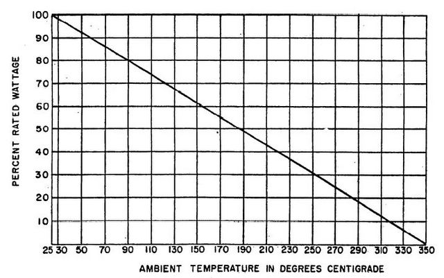
WireWound Derating Curve
Also refer to the Resistor Dictionary of Terms.
How to derate an Adjustable WireWound Resistor.
Additional information may be found on the Guideline for Derating Electronic Components
Home Page
Sunday, March 19, 2006
PWB Ground Potential

PWB Ground Potential Graph
This is a graph showing how the ground potential varies as it moves from a single point ground connection. A single point ground connection eliminates potential ground loops. How ever; a single point ground connection also does not provide a good ground potential to all points of the circuit board.
Ground loops cause unintended currents to flow in connections which should have zero current flow. Unintended current flowing in a circuit is called noise, because that current flow was not designed into the circuits operation. Avoid Ground loops or multiple circuit to ground connections in your design.
Many circuits can tolerate the rise or difference in ground potential depicted in the picture. Locate analog devices near the ground strap, and push digital devices away. An Analog IC may require a near perfect reference, while digital devices will tolerate a much larger change in the ground potential. For additional reference data of Printed Circuit Boards, check out PCB Terms and Definitions.
PWB Information
Tuesday, March 14, 2006
Magnetic Declination Over the World Chart

Magnetic Declination Over the World
This post is in support of the Direction Sensor Manufacturers page.
Direction Sensors are Two-axis or Three-axis magnetic compasses that measure earth's magnetic field.
Sunday, March 12, 2006
VoIP Phone
I added a new page for USB IP Phone Manufacturers which handle VoIP phone connections. One way to save long distance phone charges.
Friday, March 03, 2006
PWB Internal Trace I Capacity
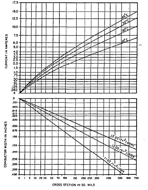
PWB Internal Trace Capacity
The chart above shows the amount of current an Internal trace on a printed wiring board can handle. The table provides the current rating based on trace cross section in square mils, temperature rise and current in amperes.
For example; if the trace width is 100 sq mils, that trace can accept between 1.5A and 4 amps depending on the acceptable temperature rise.
There are a number of pages on the web site that cover Printed Wiring Board issues, but these two links point to all of them: Refer to the page covering PWB Terms or
PWB Information
Tuesday, February 28, 2006
CRT Operation
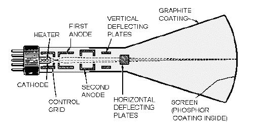
CRT Function
Internal break-away view of a CRT [cathode ray tube].
Terms and definitions have also been added related to CRTs.
Monday, February 27, 2006
PWB Mimimum Annular Ring
Two views of minimum Annular ring for printed wiring boards. The first graphic is for an internal pad, while the second graphic is for an external pad.

Internal Mimimum Annular Ring


External Minimum Annular Ring
For more information on Minimum Annular Ring refer to the definition of Minimum Annular Ring, or see here PWB Information.
The site covers electrical engineering topics.
FYI; The dictionary of PWC and PWB terms has been updated.
.
Sunday, February 26, 2006
PWB Etched Copper Current Capacity

PWB Etched Copper Current Capacity
The chart above shows the amount of current an External trace on a printed wiring board can handle. The table provides the current rating based on trace cross section in square mils, temperature rise and current in amperes.
For example; if the trace width is 100 sq mils, that trace can accept between 3.5A and 10 amps depending on the acceptable temperature rise.
Key Phrase:
How much current will a trace handle.
What is the current rating of a trace.
What trace width will handle a certain amount of current.
For more information refer to the page covering PCB Terms. For a large listing of Printed Circuit Card definitions.
Addition PWB Information
Robots/Spiders visitors

Hits from Spiders are not counted in the page counter the site uses. What is interesting is the amount of bandwidth required from these robot hits. I do have to pay for bandwidth.
For the robots listed below, and there are many others hitting the site, the required bandwidth used was; 262.82 MB [Mega Bytes]
Inktomi Slurp: 5213 hits, 27.81 MB of Bandwidth.
Google AdSense: 4306 hits, 61.63 MB of Bandwidth.
Googlebot: 3777 hits, 24.56 MB of Bandwidth.
Unknown robot (identified by 'crawl'): 2223 hits, 28.77 MB of Bandwidth.
MSNBot: 1959 28.78 MB of Bandwidth.
Unknown robot (identified by 'spider'): 1793 hits, 22.79 MB of Bandwidth.
MSIECrawler: 1773 hits, 10.50 MB of Bandwidth.
WISENutbot: 1222 hits, 18.31 MB of Bandwidth.
AskJeeves: 1080 hits, 16.97 MB of Bandwidth.
Alexa: 641 hits, 9.13 MB of Bandwidth.
GigaBot: 580 hits, 8.48 MB of Bandwidth.
Lycos: 303 hits, 5.09 MB of Bandwidth.
http://www.interfacebus.com
Friday, February 24, 2006
Low Page Hits
This is a list of some of the pages that are recieving less than 100 page hits this month. There are other pages, but many are new page address so I can understand that. These pages are older and in some cases contain information in common use so they should be seeing higher numbers..
IndustrialPCI
RS366 Bus
GDDR DIMM
HPPI Bus
HSSI Bus
HIC Bus
IP Cores
Battery Control ICs
knobs
Speakers
MIL-STD-83723.
I can only assume that for some reason these pages have a poor showing on the search engines..
Tuesday, February 21, 2006
Types of USB Devices
I took a look at some USB devices I was kind of supprised to find so many different options in a USB interface. USB stands for Universal Serial Bus. Here some different USB functions:
USB Docking Station {brings a USB port to your desk top}
USB Hub {finger stick or via a cable ~ brings Hub to desktop}
USB Card Reader
USB Flash Drive
USB Floppy Drives [External FDD]
USB WebCam
USB Speaker
USB IrDA Adapter
USB Bluetooth Adapter
USB 802.11 Adapter [WiFi]
USB Audio Interface
USB Mice / Keyboard
USB Gadgets: Heated Slippers, Gloves, Beverage Chiller
I don't think I would allow my computer to be over-heated by allowing heated gloves to draw power from my computer via the USB interface.
Manufacturers of computer gear can be found on this page: Computers and Peripheral Manufacturers.
When I wrote, years ago, it seemed odd to see some of these devices but not in 2011
.
Saturday, February 18, 2006
PCIe 1x
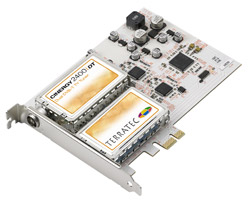
PCIe 1x TV Tuner
PCIe 1x cards are now shipping. [PCIe = PCI Express]
Terratec; Digital TV via Antenna with Stereo-Sound, Dual-Tuner (1x PCIe)
PowerColor Computer Inc; multimedia center / TV Tuner (1x PCIe)
Video Card (1x PCIe)
SIIG; PCIe 2-Port SATA II RAID Card (1x PCIe)
[there are tons of PCIe 16x video cards]
Additional PCIe card manufacturers may be found here:
http://www.interfacebus.com/COTS_Board_Manufacturers.html
Thursday, February 16, 2006
Wireless Extender Working
It seems like the wireless network extender is now working. My laptop computer sees to separate wireless links in my house, both with my net name. So the site survey window show two separate wireless nets each with a different signal strength, and they each vary to a different degree as I move around the house.
Now the GUI does have a connect switch, so I have to wonder if I need to connect to the stronger station, or the network will connect me. That's my next test of the LinkSys Wireless Extender; WRE54G
I also wonder if the Wireless-B router [BEFW11S4] is the reason for the slow connect time. It does seem like it takes awhile for the computers to see each other. Maybe I need a Wireless-G router.
Use the faq link on http://www.interfacebus.com to surf to the operational computer page ~ listing all the gear.
Wireless Repeater again
I took a look at the wireless extender tonight. Once I turned on my desk top computer I noticed the extender showed a red light ~ no network connection.
After awhile I hit the Auto config button on the WRE54G and the LED went blue indicating it connected to the network.
How ever I have the same situation as last night. The laptop indicates the wireless connection is great via windows, but the Linksys shows no connection bars indicating a bad connection [but connected]
So, it's still not working tonight. Five minutes was about all the time I put into it tonight...
Wednesday, February 15, 2006
Wireless Repeater Up-date
I was not to surprised to find that my laptop did not find my network tonight when I turned it on. Windows found a connection but the Linksys PC card did not?
So, as normal the notebook computer did not see the Linksys wireless router, and it did not see the Linksys wireless extender either.
I have to wonder what the actual range of this gear is [measured in inches], or if one wall really makes so much difference, if I have a set-up issue that disappears when I re-boot my computers, or if I still have a mis-match in my config file. ~ it did seem to be talking last night.
The Linksys [Cisco Systems] wireless gear used in the system is:
Wireless Broadband Router BEFW11S4 (Wireless-B)
Wireless Notebook Adapter WPC54GS (Wireless-G)
Wireless Range Expander WRE54G (Wireless-G) ~ not working
Wireless PrintServer WPS54G (Wireless-G) ~ not working
Of course running interfacebus.com leaves me little time to spend trying to get this stuff to work ~ yet another week-end project.
I really don't want to call the help line again, but I may have to.
Tuesday, February 14, 2006
Wireless Repeater
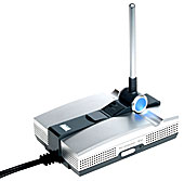
Wireless Expander
I received my new Linksys WRE54G Wireless Expander tonight. I'm still working on it and not sure if it's working yet. I was line-of-sight with it, with my laptop six feet away, but still the setup program would not find the expander.
The WRE54G operates over 'B' [IEEE802.11b] or 'G' [IEEE802.11g], I hope.
I purchased the range expander [repeater] because my Laptop just one room away would not see my wireless network router and desktop, which keeps me on my desktop more then I would like.
This week-ends project is to get the wireless printer server working [from the last post].
Tuesday, February 07, 2006
New Wireless Print Sever
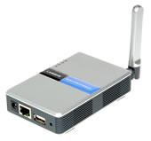
Wireless Print Server
I got a new wireless printer server for my printer tonight. The printer server is the WPS54G from Linksys. The server operates over 802.11g [2.4GHz] and connects to the printer over USB [or maybe Ethernet].
I tried to connect it up but the system never saw the printer server. Not a real surprise, as no wireless linksys device has worked the first time. ~ Or it could be that I had the pinter pluged in to the wrong port on the router.
So it's two days later and I still can't get the printer server to work. I've tried powering up the printer and server in differnet orders, changing the printer/router port. The printer still prints?
Monday, February 06, 2006
Un-interruptible Power Supply
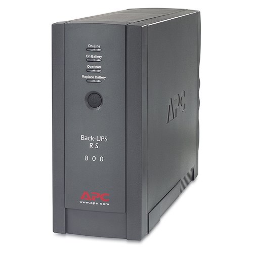
UPS
This is the UPS I used with my system. The UPS is produced by APC, and the model number is XS800-BLK. The UPS can support 540 watts / 800VA. The unit has 7 AC output connections, all AC outputs are NEMA 5-15R style connectors. Three of the outputs are surge protected only, while the other four have battery backup protection.
The unit also has two 10/100 Ethernet ports, and two phone ports which are protected.
The specification indicates a total backup time of 17 minutes at half load and 5 minutes at full load. I turn the system off with in a minute when I lose power for more then a brown-out.
The system has worked well for two years now. I'm thinking about up-grading.
Power Connector Manufacturers
Wednesday, February 01, 2006
Cost of running a Web Site
Web Site Cost
I ran some numbers last night trying to figure the amount of money it costs to run this web site.
I always have a fairly new computer, and these numbers include the cost of the Alienware PC I purchased in March of last year. However; all though I do try and get a high-end PC, I do not buy Gamer PC's ~ i.e. dual $400 video cards. I try and put the money into a higher speed processor instead.
Any how, the numbers indicate that I spent $3546.52 on computer related products last year [2005]. That number does not include the new Laptop computer I purchased last year because I have yet to find the receipt. So, over $4000 to type on a keyboard.
In fact if I had not up-graded my hosting contract the figure would be much greater. The cost to host the web site now, compared to early last year is reduced by a factor of 10 ~ as I was being fined each month for going over my bandwidth.
The Personal Computer data is here; interfacebus: Desk Top PC.
Of course the web site I run is http://www.interfacebus.com interfacebus
Tuesday, January 31, 2006
Web Site Hits comparison
In 1999 this web site received 32,100 visitors. That number was exceeded in just 8 days this year.
In 2000 this web site received 80,000 visitors. That number was exceeded after just 18 days this year.
In 2001 this web site received 131,300 visitors. That number was exceeded after just 31 days this year.
The year 2002 received 221,900 visitors. That number was exceeded after just 49 days this year.
The year 2003 received 249,164 visitors. That number was exceeded after just 55 days this year.
The web site referred to is http://www.interfacebus.com and not this blog address.
http://www.interfacebus.com/
Monday, January 23, 2006
Brother MFC-5840CN does not Scan
So I tried to scan a document the other night on my new printer/scanner. Well I could not get it to work ~ printing seems to work. I dumped my working [scanning] HP printer because I wanted a flat-bed scanner. So I kind of wanted the Brother MFC-5840 to scan my documents. Well, that's just not working yet.
I looked at the manual, and the scanning function is not mentioned [see the CD] ~ not a good sign. The Doc's refers me to the Paper-port software ~ also not a good sign. I already have a flat-bed Paper Port scanner. The reason I don't use the Paper Port flat-bed scanner is because Paper Port does not support it's own scanner after Windows 2000 [or so]. The flat bed scanner from Paper Port is junk.
I went out to the Brother web site. My issue is listed in the FAQ. I need to re-boot, and / or, re-loaded the software. Which I did..... [no help found]
Would I recommend the 5840, NO
Would I recommend the MFC-5840, NO
Would I recommend a Brother Printer, NO.
Friday, January 20, 2006
Lap-Top Computer up-grade
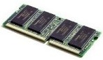
SODIMM
I added another 256MB memory stick to my lap-top tonight. That brings my memory to 512 Mega-Bytes, via two 256 Mega-byte SO DIMMs.
It took a while to get the SO-DIMM installed ~ I had to go out to Notebook for dummies to figure it out. So install at 45 degrees and push works.
The lap-top appears to work much faster now with twice the memory. The memory type is PC2100.
Wednesday, January 18, 2006
Digital Media Card reader
The Brother MFC-5840 Printer comes with a Digital Card Reader. The card reader contains three card slots for the following flash media [links are to interface descriptions]:
Compact Flash
SmartMedia
Memory Stick
x-D Picture Card
Secure Digital
While the main page which contains links to a number of different Flash Media types is located here
The three card slots accept a number of different flash cards. One card slot accepts a CF [Compact Flash] card [type I only]. One slot accepts either a x-D Picture Card or a SmartMedia card [3.3v only], while the final card slot takes either Memory Stick or Secure Digital cards. Using adaptors [not supplied] I can also use a miniSD and a Memory Stick Duo card.
I really do not have an application that uses any of these flash cards, but the option was provided on my PC for only $10, so I got the reader there and the printer.
So far, I would recommend the Brother MFC-5840CN multi-function printer. The printer is not shipped with an Ethernet or USB cable. The printer does ship with all four ink colors.
Tuesday, January 17, 2006
New Printer / Fax / Scanner

5840 Brother Printer
I purchased a new multi-function printer today to replace the outdated HP printer I now have.
The new printer is manufactured by Brother International Corporation, the model number is 5840. This is an inkjet printer, plus it will Fax, Print, Copy, Scan, PC Fax, and PhotoCapture what ever that is.
I wanted a flat-bed scanner which the HP BJC-600 did not have. I had to hope for the best on the rolled-head scanner using the HP printer. That printer also had a IEEE-1284 interface.
Any way, the major features other the printer include either a USB Bus and/or an Ethernet Bus interface, a RJ45 33.6k fax connection, and a Digital Media Card reader.
This is a black and White [B/W] or color machine. It also has two paper trays which the HP did not.
Saturday, January 14, 2006
More new pages
I added a few more pages today. The
ATCA Board Manufacturers page lists a dozen card manufacturers.
The ATCA Express Board Manufacturers page which does not yet have any manufactures, and the CompactPCI Express Board Manufacturers, also with no listed companies.
AdvancedTCA has been around for a few years, the other standards are newer.
There is another blog that I run that provides links to the new pages that are added to the web site: New Page Additions.
Wednesday, January 11, 2006
Two new page additions
I added two new pages tonight:
CompactTCA
MicroTCA
Both pages are just a copy of the cPCI page for tonight, but I should have time this week end to fix up the pages and add the correct information.
Monday, January 09, 2006
Serial SCSI
The Serial Attached SCSI [SAS] Bus defines Physical layer, PHY Layer, Link Layer, Port layer, and Application Layer. SAS may also just be called Serial SCSI. The Physical Layer consists of two sets of differential lines, one receive set and one transmit set [4-wire total]. The PHY Layer connects the differential Transmitter and Receiver circuits [ICs] to the Physical Layer, which defines the cable, connector, and transceiver [Transmitter / Receiver] characteristics. The external connector will accept 4 physical links, while the cable may hold between 1 and 4 physical links. Internal connectors are also defined. Two data rates are defined: 1.5Gbps and 3.0Gbps over a 100 ohm [+ 15 ohm] differential impedance cable. SAS uses the Serial ATA physical interface, including the connector receptacle and connector plugs.
SAS transmits data using 8B/10B at a maximum level of 1.2 volts [Tx voltage = 800-1600mV], [Rx voltage = 275-1600mV]. SAS uses big-endian, while SATA uses little-endian byte ordering. SAS uses a 32 bit CRC. Like SATA, SAS uses LVDS
Friday, January 06, 2006
SAS Roadmap
I had a look at the STA road map [SCSI Trade Association]. Here are the details;
Ultra 320 SCSI [2002 to 2009]
SAS 3 Gbps SCSI [2004 to 2011]
SAS 6 Gbps SCSI [2007 to 2012]
SAS 12 Gbps SCSI [2011 to 2014]
These dates are approximate. 'SAS' stands for Serial Attached SCSI
This page has a description of Serial SCSI;
http://www.interfacebus.com/Design_Connector_Serial_SCSI_Bus.html
And this page has a description of Parallel SCSI;
http://www.interfacebus.com/Design_Connector_SCSI.html
Both pages resides on:
http://www.interfacebus.com/
[Updated 1/30/2010] The most recent road map I've seen dates to 2009 and shows almost no SCSI drives projected to be sold by 2009, while this one indicated SCSI 320 in demand. I guess things changed a bit.
Thursday, January 05, 2006
Laptop Memory Up-grade
SODIMM
My Notebook computer [HP ze4805wm]contains one 256 MB SO-DIMM [200-pin]. The SO-DIMM style is PC2100. The clock speed of PC2100 is 266MHZ.
The part number for the memory module which was supplied with the laptop is; Hewlett Packard (HP) Laptop / Notebook Memory: 317435001 / 317435-001. I was never able to find the cas latency.
I discovered I have two SO-DIMM slots so the plan is to up-grade the system with another 256MB PC2100 SO-DIMM, giving me 512MB of system memory. This allows me to keep the orginal 256MB. Ranging around $30 to $70 per stick.
SO DIMM = Small Outline Dual In-Line Memory Module.
Wednesday, January 04, 2006
Wireless USB
I added a new page which will cover Wireless USB. The page is located at:
http://www.interfacebus.com/Wireless_USB.html
It's really still just a copy of the USB page, but that's what wireless USB is [with out a cable]. So I'll be fixing up that page over the coming days.
Tuesday, January 03, 2006
USB Flash Drive
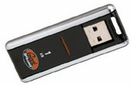
Flash
I got a new 1G Byte USB flash drive today.
I tried to back-up some data to my laptop yesterday and filled my other Flash drive. This new one even has pre-installed programs ~ like I have time to use them.
So now I have a:
32MB Buslink USB Flash drive
256MB Impact USB Flash drive
1GB Geek Squad USB Flash drive
Sunday, January 01, 2006
Serial Attached SCSI [SAS] Bus
The Serial Attached SCSI [SAS] Bus defines the Physical layer, PHY Layer, Link Layer, Port layer, and Application Layer. SAS may also just be called Serial SCSI. The Physical Layer consists of two sets of differential lines, one receive set and one transmit set [4-wire total]. The PHY Layer connects the differential Transmitter and Receiver circuits [ICs] to the Physical Layer, which defines the cable, connector, and transceiver [Transmitter / Receiver] characteristics.
The external connector will accept 4 physical links, while the cable may hold between 1 and 4 physical links. Internal connectors are also defined. Two data rates are defined: 1.5Gbps and 3.0Gbps over a 100 ohm [+ 15 ohm] differential impedance cable. SAS uses the Serial ATA physical interface, including the connector receptacle and connector plugs.
SAS transmits data using 8B/10B at a maximum level of 1.2 volts [Tx voltage = 800-1600mV], [Rx voltage = 275-1600mV]. SAS uses big-endian, while SATA uses little-endian byte ordering. SAS uses a 32 bit CRC. Like SATA, SAS uses LVDS
Tuesday, December 27, 2005
IDE Hard Drive Bus
Nominally called the IDE (Integrated Drive Electronics) bus; how ever it's more correctly known as the ATA (Advanced Technology Attachment) specification [ATA Bus]. The IDE bus is used in Personal Computers [PCs] as a hard-drive or peripheral bus to interconnect the PC mother board and a hard drive. The IDE bus is a Parallel bus. With the introduction of the Serial ATA [SATA] specification Parallel ATA [IDE] is now being called PATA.
The specification has been up-graded a number of times each building on the past specification. ATA-1 and 2 were single documents, but like SCSI, after ATA-2 the specification was divided into a number of different documents. Most maintain backward compatibility, keeping in mind the cable changed. Each new version of the standard saw an increase in bus speed. The data transfer rate is shown after each version listed below. The current maximum IDE bus speed is 133MBytes/sec [133MBps].
Data is passed Single-Ended,via data line and ground. Only the 40 pin connector pin out are referenced below, which are used on 3.5-inch drives, but there is also a 50 pin connector used on 2.5-inch drives. The 50 pin connector adds the power and Master/Slave functions. PCMCIA uses a 68 pin connector. A graph showing the difference between ATA and Ultra ATA timing is shown on the below. The standard defines a single Host or adaptor which connects to one [device 0] or two [device 1] devices in a daisy chained configuration. The IDE, ATA connector pinout is listed in the table below. Note; there is text to decode the 80 pin cable onto the 40-pin connector.. There are a number of versions of the ATA bus, with each of the different versions listed below. The Serial ATA: which replaced the ATA bus is listed on its own page. Details for each bus version are listed below. A graphic which provides a comparison of all the different IDE interfaces listed here is provided on the HardDrive Interface Speed page.
ATA-1 (IDE), [Obsolete] 8.3MBytes/sec, 8 or 16 bit data width, 40 pin data ribbon cable/connector. With a maximum of 2 devices on the bus. Using PIO Modes 0, 1 or 2. Performed no bus error correction. The ATA-1 specification was released in 1994, and was withdrawn in 1999.
ATA-2 (EIDE, or Fast ATA), [Obsolete] 16.6MBytes/sec, 8 or 16 bit data width, 40 pin data ribbon cable/connector. With a maximum of 4 devices on the bus. Using PIO Modes 0, 1, 2, 3, or 4. The ATA-2 specification was released in 1995 and was withdrawn in 2001.
ATA-3, 16MBytes/sec, 16 bit data width, 40 pin data ribbon cable/connector. Using PIO Modes 0, 1, 2, 3, or 4 and Multiword DMA modes 1 and 2. Runs with 120nS Strobes (rising edge to rising edge). Includes CRC.
ATAPI (ATA Packet Interface)is the CD-ROM side of the interface. It uses the same connector as ATA, and adds 1 for analog and 1 for digital audio. The ATA-3 specification was released in 1997 and was withdrawn in 2002.
ATA-4 Ultra-ATA/33, 33MBytes/sec, 16 bit data width, 40 pin data ribbon cable/connector. Using PIO Modes 0, 1, 2, 3, or 4 and Multiword DMA modes 1 and 2 and Ultra DMA modes 0, 1, and 2. Runs with 120nS Strobes (rising edge to rising edge), but used both edges of the Strobe producing an effective 60nS Strobe rate. 33MBps Transfer speed = [(1/120nS) x 2 bytes x 2]. Where 120nS cycle time is 4 clock periods at 30nS each. Added CRC checking. The ATA-4 standard was released in 1998.
ATA-5 Ultra-ATA/66, 66MBytes/sec, 16 bit data width 40 pin data connector/80 pin cable, with the additional 40 new pins being Ground. The new cable allows ATA/66 to run at a faster rate then ATA/33. Using PIO Modes 0, 1, 2, 3, or 4 and Multiword DMA modes 1 and 2 and Ultra DMA modes 0, 1, 2, 3 and 4. Runs with 60nS Strobes (rising edge to rising edge), but uses both edges of the Strobe producing an effective 30nS Strobe rate. 66MBps Transfer speed = [(1/60nS) x 2 bytes x 2]. Where 60nS cycle time is 2 clock periods at 30nS each. The ATA-5 standard was released in 2000.
ATA-6 Ultra-ATA/100, 100MBytes/sec,16 bit data width 40 pin data connector/80 pin cable, with the additional 40 new pins being Ground. Using PIO Modes 0, 1, 2, 3, or 4 and Multiword DMA modes 1 and 2 and Ultra DMA modes 0, 1, 2, 3, 4 and 5. 100MBps Transfer speed = [(1/40nS) x 2 bytes x 2]. Where 40nS cycle time is 2 clock periods at 20nS each. The ATA-6 standard was released in 2002.
ATA-7 Ultra-ATA/133, 133MBytes/sec,16 bit data width 40 pin data connector/80 pin cable, with the additional 40 new pins being Ground. Using PIO Modes 0, 1, 2, 3, or 4 and Multiword DMA modes 0, 1 and 2 and Ultra DMA modes 0, 1, 2, 3, 4, 5 and 6. 133MBps Transfer speed = [(1/30nS) x 2 bytes x 2]. Where 30nS cycle time is 2 clock periods at 15nS each. The ATA-7 standard was released in 2005. With the introduction of Serial ATA, this is the last expected update of the IDE [PATA] bus. SATA: is faster, and requires a smaller cable, which means better air flow in the Chassis.
Serial ATA: (Ver 1.0) High Speed Serialized AT Attachment
Serial version of the IDE [ATA] spec. Uses a 4 conductor cable with two differential pairs [Tx/Rx], plus an additional three grounds pins and a separate power pin. Data runs at 150MBps [1.5GHz] using 8B/10B encoding and 250mV signal swings. Serial ATA is not compatible with the IDE [Parallel ATA] because the connectors are different, the voltage levels are different, and data format is different [SATA sends a bit at a time while PATA sends 16 bits at once]. SATA will not interface with the IDE bus. No cable can be made to connect SATA with IDE. However a converter may be purchased which translates SATA to PATA. One module appears as a 2" x 2" board, for $50 and converts IDE controllers 66/100/133/150 MB/s to Serial ATA 150.
Regardless of the electrical interface the drives uses, there are also Solid State Drives available that do not require a platter. Or just Hybrid Hard Disk Drives that still use a platter, but have a greater amount of Flash Memory.
Saturday, December 24, 2005
Ground Bounce
Ground Bounce: defines a condition when a device's output {really a number of outputs} switches from High to Low and causes a voltage change on other pins. The problem is cause by the large current flow through the ground pin which develops a voltage drop over the lead inductance. This voltage drop on the ground line creates two main problems; first it rises the chip off ground [0 volts] potential which increases the devices input threshold level, and increases the voltage level on an output pin which is not switching. Because a quiet output is effected by the other switching outputs, this is also called Simultaneous Switching Noise. It's really a question of loss of noise margin. The faster the slew rate of the logic family, the worse the problem becomes.
With Glue Logic, the ground pins may have been moved around to reduce the inductance. Using a surface mount device instead of a Through Hole will reduce the lead inductance. For FPGA's with hundreds of possible output pins the situation may change, and it's more up to the designer. Start a noise budget to determine if the ground bounce [rise in ground potential] effects the design. The voltage developed over the ground lead is proportional to the rate of change in current, so the faster the logic family the worse the problem becomes: V = L * [di/dt]. The more outputs switching at the same time, the larger the current value, and greater voltage bounce. Also occur when the outputs switch from a 0 to a 1 but to a much smaller degree. Series termination of the line is one method of reducing ground bounce. Series termination resistors slow the rate of change of the output, and so reduce the instantaneous current on the ground line. Also Resistor Pull-Ups on the line cause the ground bounce voltage to increase. The pull-up resistor allows the load capacitor to charge to it's full value, so as the line switches maximum current is delivered back to the driver. Eliminate pull-up resistors on devices with an issue, use pull-down resistors or series resistors if possible. Reducing the loading on the driver also reduces ground bounce. Ground Bounce may also be called Ground Lift.
Friday, December 23, 2005
The future of RS-232

New I/O Panel Format
This post consolidates a few other postings about the RS-232 [EIA-232] interface going obsolete.
The picture shown above depicts the back panel I/O found on some newer mother boards. Comparing that picture with the one at the bottom of this post and the difference becomes obvious. The RS-232 and IEEE-1284 connectors have been replaced by a heat sink. The video interface has also been removed.
It makes perfect sense to remove the RS232 interface and the other two connectors from the back of computers. The video interface is normally found on the video card, so the 15-pin D-sub connector is not required. Many video cards ship with a DVI and VGA connector, so why have another one the mother board. The 25-pin parallel port connector is out dated. Many new printers ship with an Ethernet port which is much faster then the IEEE-1284 interface bus. With over 6 USB ports to handle any required peripheral, and 2 circular DINs to accommodate a keyboard and mouse the RS-232 interface is just not required.
When you add all this up, the benefit to removing these out-dated interfaces translate to higher speed peripheral connections, reduced cost by eliminating 3 large connectors, and the better use of the motherboard back panel.
In the three different mother boards I looked at the free space was taken up by a heat sink and fan. Both used to vent heat from the chip set ICs
The Apple computers removed the RS232 bus and IEEE-1284 [Printer Port] bus some time ago.
Links with detailed information about the interfaces:
EIA-232
IEEE-1284
VGA
DVI
The RS232 interface is dead and should not be used for new designs. The IEEE-1284 interface is dead. The 15-pin VGA interface is dead on the newer mother boards. These interfaces should start to disappear next year

Mother Board I/O
Thursday, December 22, 2005
AGP Bus
The AGP [Accelerated Graphics Port] is a Point-to-Point [Chip-to-Chip] interface using 1.5 Volt or 3.3V signaling. The main use of AGP is as a Local Video bus in IBM compatible Personal Computers [PCs]. The AGP interface bus is based on the PCI [Peripheral Component Interface] spec, using the PCI specification as an operational baseline. The AGP specification adds 20 additional signals not included in the PCI bus. The AGP specification defines the Protocol, Electrical and Mechanical aspects of the bus. Refer to this page for a comparison of Video bus through-put for different expansion buses.
The Mechanical definitions include a connector and AGP Board [Add-in card]. The Card sizes and 1.5v and 3.3v connectors are also defined within the spec. There are five connectors defined: AGP 3.3v, AGP 1.5v, AGP Universal, AGP Pro Universal, AGP Pro 3.3v, and AGP Pro 1.5v.
PCI and AGP boards are not mechanically interchangeable.
The AGP 1.0 spec defined 1x and 2x speeds with the 3.3v keyed connector.
The AGP 2.0 specification defined 1x, 2x and 4x speeds with the 3.3v, or 1.5v keyed connector or a 'Universal' connector which supported both card types.
The AGP Pro specification defined 1x, 2x and 4x speeds with the 3.3v, or 1.5v keyed connector or a 'Universal' connector which supported both card types.
The AGP 3.0 specification defined 1x, 2x, 4x and 8x speeds with the 1.5v keyed connector or a 1.5v AGP Universal / Pro connector.
Each up-grade is a supper-set of the 1x mode, so 4x will also support the 1x speed. The base clock rate is 66MHz, but to achieve to 2x, 4x, and 8x speeds the clock is doubled each time. AGP uses both edges of the clock to transfer data.
AGP (1x): 66MHz clock, 8 bytes/clock, Bandwidth: 266MB/s [3.3V or 1.5V signal swing]
AGP 2x: 133MHz clock, 8 bytes/clock, Bandwidth: 533MB/s [3.3V or 1.5V signal swing]
AGP 4x: 266MHz clock, 16 bytes/clock, Bandwidth: 1066MB/s [1.5V signal swing]
AGP 8x: 533MHz clock, 32 bytes/clock, Bandwidth: 2.1GB/s [0.8V signal swing], still uses 1.5 volt motherboard power
The AGP data bus may be 8, 16, 24, 32, or 64 bits. Due to timing requirements the maximum bus length is 9". The trace impedance is specified as 65 ohms +/- 15 ohms (no termination resistor is specified). For the 8x speed the bus requires a parallel termination or 50 ohms. Some lines may require a Pull-Up Resistor to insure the lines come out of reset in the proper state. The AGP Interface is optimized for FR4 PCB designs. Both 4 layer and 6 layer PCBs have been studied.
AGP 2.0 pin out, 2 rows of 66 finger [pins]. The Pin Outs for AGP 3.0 specification differ from the AGP 2.0 Standard.
Not all AGP cards will work in all AGP slots. Use the table below, to determine if an AGP board will function in a particular motherboard. The AGP pinout list is provided lower down the page.
Wednesday, December 21, 2005
RAID

Hard Disk Drive Storage
I found a comparison test showing the performance difference between having RAID 0 and having no RAID at all. The term RAID means; Redundant Array of Inexpensive Disks. RAID 0 is the 'Stripping' form of RAID ~ each disk of a two disk set gets half the data speeding the process of reading/writing to disk.
Unfortunately the test showed that when using normal office software [which is what I use] there really was no difference in performance. So why purchase another $200 HDD for just 1 or 2% speed increase. So, my next computer will not use RAID 0, however I may still set it up for RAID 1.
The test did show that my Seagate Barracuda drive is much slower then my Western Digital Raptor.
Monday, December 19, 2005
Automotive Buses
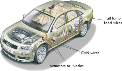
CANbus Interface
Ok I have to admit there are a lot of Automotive Buses, I list more then a dozen. Sure some are showing their age, but I have to track them all.
I updated one of the Automotive and Vehicle Buses sub pages tonight, and then the main Auto page. The CANbus still rules, but the audio/video buses are starting to make head-way.
Making things harder to track is the fact that many car makers run multiple buses ~ which makes sense because the buses are aimed at different areas of the car market.
It's all about number of signals, connector type and protocol....
Sunday, December 18, 2005
Serial ATA Hard Drive Interface
The Serial ATA bus [SATA] is the serial version of the IDE [ATA] spec. SATA uses a 4 conductor cable with two differential pairs [Tx/Rx], plus an additional three grounds pins and a separate power connector. Data runs at 150MBps [1.5GHz] using 8B/10B encoding and 250mV signal swings, with a maximum bus length of 1 meter . Later SATA enhancements move the data transfer speed to; 300MBps [3.0Gbps], and then 600MBps [6.0Gbps]. The current speed for SATA is 300Mbps [3Gbps]. Shielded external SATA [eSATA] data cable runs out to a maximum of between 3 feet and 6 feet. eSATA cables are used external to the chassis or case.
SATA Protocol
The SATA Frame structure used between Host and Device is shown in the graphic below. The frame is made up of multi Dwords, which are in turn encapsulated by flow control and CRC information. The SATA frame begins with a Start-of-frame [SOF]. The SOF is followed by the Frame Information Structure [FIS]. Then the Cyclic Redundancy Code [CRC] is placed in the frame. The final block in the message is an End-of-Frame [EOF].
SATA uses a 32bit CRC [calculated over the contents of a (FIS) Frame Information Structure], stored as the 'Dword'. The 32-bit CRC polynomial is X32+ X26+ X23+ X22+ X16+ X12+ X11+ X10+ X8+ X7+ X5+ X4+ X2+ X + 1.
SATA Electrical
Serial ATA uses LVDS [EIA/TIA-644] with voltages of 250mV; while the obsolete parallel ATA interface is based on TTL signaling levels and rates. Serial ATA is a point-to-point interface where each device is directly connected to the host via a dedicated link. Because Serial ATA uses a dedicated link, adding another drive to the computer will have no impact on bandwidth. With Serial ATA the additional hard drive uses a separate SATA link, while the older IDE parallel standard [PATA] would see a degradation in speed because the drives would share the same link band width.
The Bit Encoding used is: Non Return to Zero (NRZ) encoding for data communication on a differential two wire bus. The use of NRZ encoding ensures compact messages with a minimum number of transitions and high resilience to external disturbance. The termination resistor is 100 Ohms [+/- 5 Ohms] differential.
SATA Physical
Serial ATA uses only 4 signal pins, improving pin efficiency over the parallel ATA interface which uses 26 signal pins going between devices [over an 80 conductor ribbon cable onto a 40 pin header connector].
Serial ATA also provides the opportunity for devices to be 'hot-plugged', devices may be inserted or removed while the system is powered on. The pinout tables for Serial ATA are listed below.
The primary function of Serial ATA bus is to form an interface between the Motherboard and the Hard Disk Drive [HDD]. The Hard Drive may have a SATA connector and a legacy PATA data connector, with a legacy PATA power connector, so the device may function in either a legacy [older] motherboard or a currently produced motherboard. In this case the mother board S-ATA interface would be developed from a peripheral add-on board and not the motherboard. Power connectors on a HDD are header pins for a P-ATA interface and card-edge finger blades in the case of S-ATA. Some drive connectors shield the S-ATA power connector preventing their use, so you must use the P-ATA power pins to supply power to the drive. Terms used to describe the obsolete Harddrive interface which preceded the SATA interface include; IDE, Parallel ATA, PATA, and P-ATA.
Saturday, December 17, 2005
PCI Express Interface
The PCI Express [PCIe] bus defines the Electrical, topology and protocol for the physical layer of a point to point serial interface over copper wire or optical fiber. In addition to the Physical Layer, the PCI Express specification also covers the Transaction Layer and Data Link Layer. The Physical Layer resides with Layer 1, and the Data Link Layer resides with Layer 2 of the OSI protocol model.
PCI Express is the new serial bus addition to the PCI series of specifications. How ever the electrical and mechanical interface for PCI Express is not compatible with the PCI bus interface.
This is a serial bus which uses two low-voltage differential LVDS pairs, at 2.5Gb/s in each direction [one transmit, and one receive pair]. A PCI Express link is comprised of these two unidirectional differential pairs each operating at 2.5Gbps to achieve a basic over all throughput of 5Gbps [before accounting for over-head]. PCI Express uses 8B/10B encoding [each 8 bit byte is translated into a 10 bit character in order to equalize the numbers of 1's and 0's sent, and the encoded signal contains an embedded clock].
PCI Express supports 1x [2.5Gbps], 2x, 4x, 8x, 12x, 16x, and 32x bus widths [transmit / receive pairs]; 2.5Gigabits/second per Lane per Direction. The 8B/10B changes the data transfer numbers to 250MBps per lane, raw data [B= Bytes, b=Bits]. The reduction in throughput is accounted for under the protocol section. LVDS stands for: Low Voltage Differential Signaling.
The basic LVDS interface is a single differential link in either one or both directions. Each link requires a termination resistor at the far [receiver] end. The nominal resistor values used is 100 ohms, but would depend on the cable or PWB trace impedance used.
LVDS is a scalable bus; one uni-directional link or multiple links may be used. The LVDS graphic above indicates a 1-meter length, but the PCIe specification only allows a 20 inch trace. Refer to the LVDS page for additional information.
You can read more, and find links to component manufacturers on the PCIe page
Wednesday, December 14, 2005
New Video Interface
I found a new up-and-coming video interface today. I was a little surprised, as I figured I had already identified the replacement for DVI. I thought the new interface was P&D. There are so many video interface standards. Now I see a newer one called DisplayPort which may replace both.
I also saw that the DVI standard was frozen ~ and dead [my words]. If it's true that the DVI standard is not being worked then that would indicate that either the Plug and Display interface or the new DisplayPort may start to replace it some time next year.
Both interfaces are listed on my web site; the PC Monitor page is listed here
Monday, December 12, 2005
SpyWare Detected
I got hit by spyware software today some time around 6:00 AM. I was checking incoming web sites from one of my e-mail accounts. I run multiple Internet Explorer windows while also running Firefox. While in Firefox I notice the Internet Explorer group of windows closed. When I got around to re-opening IE I notice I had a new tool-bar ~ not a good sign.
I tried to run Spyware Doctor but it just locked up my computer, or I refused to wait more then 20 seconds for it to start. Any how, I down loaded Spyware Doctor from the web again as I assumed that the spyware had disabled the program. How ever, to my dismay the program is no longer free. I wasted 45 minutes as it slowly scanned my computer only to find out that it would detect spyware but would not remove it unless I sent them money. Of course the next thing I did was to delete Spyware Doctor.
I then disconnected my internet interface.
Tonight I down-loaded and ran to different programs; Spybot and McAfee. I ran Mcafee first, and it found 2 trojans. Finding two trogan programs is good, but they did make it a little hard to delete the program ~ I had the 30 day free program. I then ran Spybot which is free.
I always run Norton Internet Security, and it's set to always run. I assume no information was lost because they should stop any program accessing the internet with out me knowing about it ~ now I wonder.
I don't think I'm as protected ~ I will no longer run Internet Explorer unless I'm on my own web site, I'll surf the web with Firefox from now on.
I did download and run SpyWare Doctor the next day which found more spyware. I then down loaded and ran Ad Aware which only found a few cookies.
Saturday, December 10, 2005
Removing Standards Bodies from the PC
The original PC cards developed by IBM were the PC-XT bus and the PC-AT bus. The PC-AT interface was later developed as a standard by the IEEE as IEEE-P966. Today the PCI bus and PCI Express bus are controlled by the Peripheral Component Interconnect - Special Interest Group [PCI-SIG].
The AGP interface standard was developed by Intel, the motherboard design and specification is also controlled by Intel.
The old IDE hard drive standard [ATA] was controlled by the T13 working group of the InterNational Committee on Information Technology Standards. Today the serial ATA [SATA] interface is controlled by the Serial ATA International Organization.
The old SCSI hard drive standard was controlled by the T10 working group. These days Serial SCSI [SAS] retains its protocol but uses the same physical layer as SATA.
The Universal Serial Bus [USB] is controlled by another non-profit corporation.
If it's true that Firewire is moving into disfavor, then it would remove one of the last interface standards controlled by ANSI, or the IEEE. Firewire is also known as IEEE-1394. Recall that the other major bus controlled by the IEEE is the IEEE-1284 Parallel "Printer" bus, currently being obsoleted and replaced by the USB port on most new devices.
RS232 serial ports [EIA-232] are also being removed from the newest motherboard designs. More here
So in another year a new computer will not contain a card or interface controled by a national standards institute. Instead all the boards and interfaces will be controlled by 4 or 5 non-profit corporations.
Friday, December 09, 2005
Firewire Bus Support
I just read an article about how Apple had moved it's Firewire page to a sub page and that it was down graded in an intel product as well.
I don't have one device that uses Firewire. All my devices are USB; Memory, Mouse, Keyboard, Web Cam ... What did we use Firewire for. My site has a description of the Firewire bus on this page HIGH PERFORMANCE SERIAL BUS. Firewire is also know as the standard IEEE 1394.
If in fact the Firewire bus is in the process of being dumped, then there are larger issues to consider ~ as in there would no longer be any standards organizations working in the Personal Computer area. All interfaces are now controlled by other companies, more later.
System Motherboard
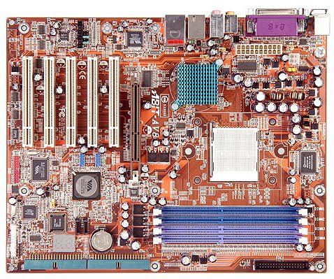
Abit Motherboard
Here is the motherboard used in the Alienware computer system. The Abit AV8 supports the AMD 939-pin processor.
The board supports four 184-pin DIMM sockets, as Un-buffered Non-ECC DIMM ~ Dual channel DDR 400/333/266. The chipset is the VIA K8T800 Pro + VT8237. The Accelerated Graphics Port connector supports AGP 8X/4X. SATA 150 Raid 0/1. An on-board PCI Ethernet Controller; LAN. On board 6-channel AC 95 CODEC for audio.
One 8x AGP slot, and 5 PCI slots
Wireless Router
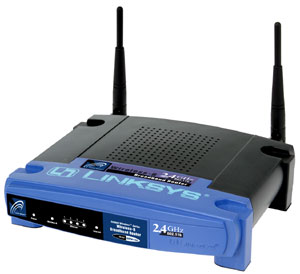
Linksys Wireless Router
The router I use is the BEFW11S4 Wireless-B broadband router from Linksys. The router is hard-wired to the desktop PC, and also to my cable modem. The wireless connection is for my laptop.
The router operates at 2.4GHz, over the old 802.11b standard [with 11 possible channels]. It has one 10/100 RJ-45 port for the cable modem and four 10/100 RJ45 switched ports.
PC Printer

HP Printer
This is the printer I use with the PC. It's a color printer, Fax machine, Scanner, and copier. The printer is the OfficeJet 600 produced by HP. I've had this printer for 5 or 6 years now and have never had a problem with it.
The Scan Resolution is 300 dpi, 1200 dpi maximum. Copy speed of 5 minutes per page in color or 1 mpp for monochrome ~ up to 99 copies can be made at once. Fax/Modem speed is 14400.
Here is a listing of Printers Manufacturers & Plotters Manufacturers
5/24/07 update; this printer has been discarded and replaced. Here is the latest printer being used.
Wednesday, December 07, 2005
Hard Drive fragmentation
I also checked my hard drives for fragmentation. The 'C' drive which holds the OS and most of the computer programs was not fragmented. The 'J' drive which holds all my web programs and HTML files was not fragmented. How ever the 'L' drive which I just set up as my external back-up hard drive was 100 % fragmented.
Having the external drive completely fragmented doesn't sound good, I've only been running the drive for a week now. Judging by the file name it's currently de-fraging tells me that the back-up software generates the back-up as some compressed file format and not a group of changed files ~ under their original files names...
Tuesday, December 06, 2005
S/PDIF Interface

S/PDIF Interface
I added a few additional comments on the S/PDIF interface page. The S/PDIF may be seen on the 5/14 audio bay shown above. The interface for S/PDIF is shown as two RCA jacks on the far left of the bay. The pic is the Sound Blaster X-Fi Platinum Sound Card used in my computer system [interfacebus: Desk Top PC].
S/PDIF Description
S/PDIF [Sony/Philips Digital Interface] is used on digital audio consumer products while the AES3 interface is used with professional products. The S/PDIF may also be listed as SPDIF. Version 2.2 of Audio Codec '97 [AC 97], released in 2000 talks about the S/PDIF interface as it relates to computer support. AC 97, which is written by intel, recommends against using S/PDIF in favor of either USB or Firewire. The AC 97 document indicates that S/PDIF is not as user-friendly as USB or IEEE 1394. S/PDIF is non-PnP, uni-directional, low bandwidth, and carries data only ( .. no indication the S/PDIF is installed or operational..). However as of the 2002 revision of AC 97 those comments have been removed.
S/PDIF uses 75 ohm coax cable with BNC Connectors. However RCA jacks are common on computer equipment. The maximum cable length is 10 meters. The output voltage level for SPDIF is 0.6 volts maximum, with input voltage levels of 0.2 volts. SPDIF signals may also be provided as TTL voltage levels. Fiber connectors are also common using TOSLINK fiber connectors. Because the IEC standard defines the characteristics of S/PDIF, the IEC specifications should be used instead of the SPDIF standard
FYI: a new standard was released by intel in 2004; High Definition Audio Specification [HD Audio]. HD Audio is not backward compatible with AC 97.
SPDIF Standard Organizations
IEC 60958-3: Digital audio interface - Part 3: Consumer applications
IEC 60958 and EIAJ CO-1201 cover both consumer and professional definitions
Saturday, December 03, 2005
LED Manufacturing Page Update

I up-dated the LED page again, and I divided it up into sections just like the Capacitor page. LED Manufacturers. LCD Manufacturers. Lamp Manufacturers.
www.interfacebus.com
Friday, December 02, 2005
Capacitor Page Up-date

I up-dated the capacitor page last night. I took the main capacitor page which included all types and divided each dielectric onto it's own page. The main capacitor page is at
Capacitor
The new sub pages are here;
Electrolytic Capacitor
Ceramic Capacitor
Plastic Film Capacitor
High Voltage Capacitor
Tantalum Capacitor
Trimmer Capacitor
