Showing posts with label PWB. Show all posts

Sunday, March 19, 2006

PWB Ground Potential


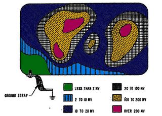
PWB Ground Potential Graph


This is a graph showing how the ground potential varies as it moves from a single point ground connection. A single point ground connection eliminates potential ground loops. How ever; a single point ground connection also does not provide a good ground potential to all points of the circuit board.

Ground loops cause unintended currents to flow in connections which should have zero current flow. Unintended current flowing in a circuit is called noise, because that current flow was not designed into the circuits operation. Avoid Ground loops or multiple circuit to ground connections in your design.

Many circuits can tolerate the rise or difference in ground potential depicted in the picture. Locate analog devices near the ground strap, and push digital devices away. An Analog IC may require a near perfect reference, while digital devices will tolerate a much larger change in the ground potential. For additional reference data of Printed Circuit Boards, check out PCB Terms and Definitions.
PWB Information

Friday, March 03, 2006

PWB Internal Trace I Capacity


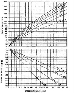
PWB Internal Trace Capacity


The chart above shows the amount of current an Internal trace on a printed wiring board can handle. The table provides the current rating based on trace cross section in square mils, temperature rise and current in amperes.

For example; if the trace width is 100 sq mils, that trace can accept between 1.5A and 4 amps depending on the acceptable temperature rise.

There are a number of pages on the web site that cover Printed Wiring Board issues, but these two links point to all of them: Refer to the page covering PWB Terms or
PWB Information

Sunday, February 26, 2006

PWB Etched Copper Current Capacity


PWB Etched Copper Current Capacity Posted by Picasa


The chart above shows the amount of current an External trace on a printed wiring board can handle. The table provides the current rating based on trace cross section in square mils, temperature rise and current in amperes.

For example; if the trace width is 100 sq mils, that trace can accept between 3.5A and 10 amps depending on the acceptable temperature rise.

Key Phrase:
How much current will a trace handle.
What is the current rating of a trace.
What trace width will handle a certain amount of current.
For more information refer to the page covering PCB Terms. For a large listing of Printed Circuit Card definitions.
Addition PWB Information