
The VME interface still seems to be in high demand. There are a number of pages which deal with the VME bus, and the manufacturers which produce components and equipment on http://www.interfacebus.com/.
The main page that deal with the topic is the VME Bus page. Additional pages include Board manufacturers, Chassis manufacturers, Backplane manufacturers, and a number of pages providing Connector Pinouts.
Friday, March 31, 2006
VME Bus
Wednesday, March 29, 2006
Switch Manufacturers Listing
I divided up the switch manufactures page into a number of switch types:
[DIP Switch Manufacturers]
[Key Switch Manufacturers]
[Miniature Switch Manufacturers]
[Push Button Switch Manufacturers]
[Reed Switch Manufacturers]
[Rocker Switch Manufacturers]
[Rotary Switch Manufacturers]
[Slide Switch Manufacturers]
[Snap-in Rocker Switch Manufacturers]
[Subminiature Switch Manufacturers]
[Tact Switch Manufacturers]
[Toggle Switch Manufacturers]
The main page for the site is at:
[www.interfacebus.com]
Tuesday, March 28, 2006
SpaceWire
I moved the information for the SpaceWire interface off the main Avionics Buses page and onto the new SpaceWire Avionics Bus page.
The SpaceWire interface uses a 9-pin cable / connector to communicate in full-duplex over a point-to-point serial communication link.
Sunday, March 26, 2006
WireWound Resistor

WireWound Resistor
The chart below depicts the temperature dereating for an Adjustable WireWound resistor. A Wirewound resistor is used in high power applications. The type of Wire wound resistor shown in the picture above is adjustable, but requires a screw driver to move the tape. This link provides Potentiometer Manufacturers
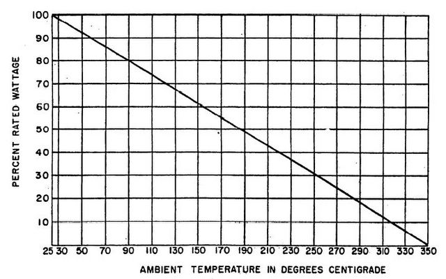
WireWound Derating Curve
Also refer to the Resistor Dictionary of Terms.
How to derate an Adjustable WireWound Resistor.
Additional information may be found on the Guideline for Derating Electronic Components
Home Page
Sunday, March 19, 2006
PWB Ground Potential

PWB Ground Potential Graph
This is a graph showing how the ground potential varies as it moves from a single point ground connection. A single point ground connection eliminates potential ground loops. How ever; a single point ground connection also does not provide a good ground potential to all points of the circuit board.
Ground loops cause unintended currents to flow in connections which should have zero current flow. Unintended current flowing in a circuit is called noise, because that current flow was not designed into the circuits operation. Avoid Ground loops or multiple circuit to ground connections in your design.
Many circuits can tolerate the rise or difference in ground potential depicted in the picture. Locate analog devices near the ground strap, and push digital devices away. An Analog IC may require a near perfect reference, while digital devices will tolerate a much larger change in the ground potential. For additional reference data of Printed Circuit Boards, check out PCB Terms and Definitions.
PWB Information
Tuesday, March 14, 2006
Magnetic Declination Over the World Chart

Magnetic Declination Over the World
This post is in support of the Direction Sensor Manufacturers page.
Direction Sensors are Two-axis or Three-axis magnetic compasses that measure earth's magnetic field.
Sunday, March 12, 2006
VoIP Phone
I added a new page for USB IP Phone Manufacturers which handle VoIP phone connections. One way to save long distance phone charges.
Friday, March 03, 2006
PWB Internal Trace I Capacity
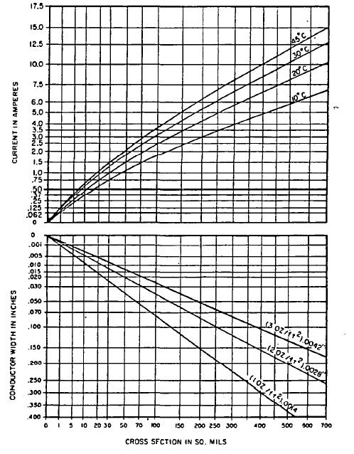
PWB Internal Trace Capacity
The chart above shows the amount of current an Internal trace on a printed wiring board can handle. The table provides the current rating based on trace cross section in square mils, temperature rise and current in amperes.
For example; if the trace width is 100 sq mils, that trace can accept between 1.5A and 4 amps depending on the acceptable temperature rise.
There are a number of pages on the web site that cover Printed Wiring Board issues, but these two links point to all of them: Refer to the page covering PWB Terms or
PWB Information